Mlewand blog Thoughts on programming.
IoT everything! A first look at ESP8266 (WiFi Witty Cloud Development) board
After witnessing some really cool automation systems recently, I’ve become excited about the possibilities that IoT brings into play. That’s why I decided to buy an ESP8266 module, however there were no convenient tutorials on how to actually get started. It wasn’t hard with figuring it out - but it make sense to share it, so you can get things going with ease.
Since there’s a great integration for Arduino IDE, we’ll use that to create and upload the software.
Hardware
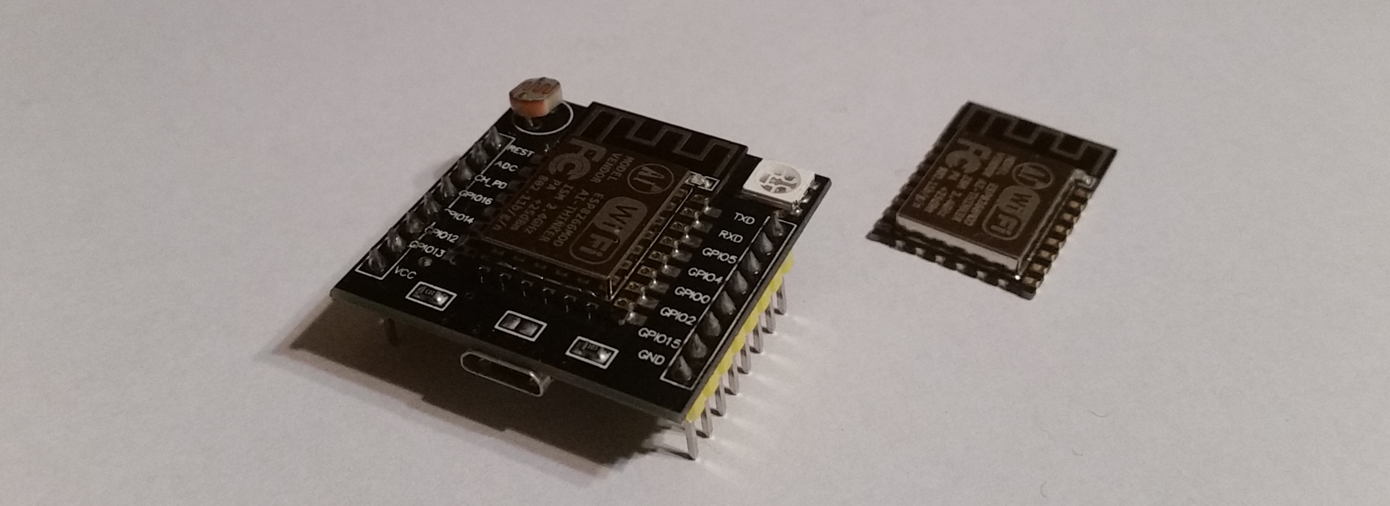
Before we start programming let’s just quickly summarize what the Witty Mini provides in terms of the hardware.
- Main board - left side - this is where the ESP8266, WiFi microcontroller, sits on.
- USB board - right side - that’s where you plug your USB driver when uploading your code to the MCU.
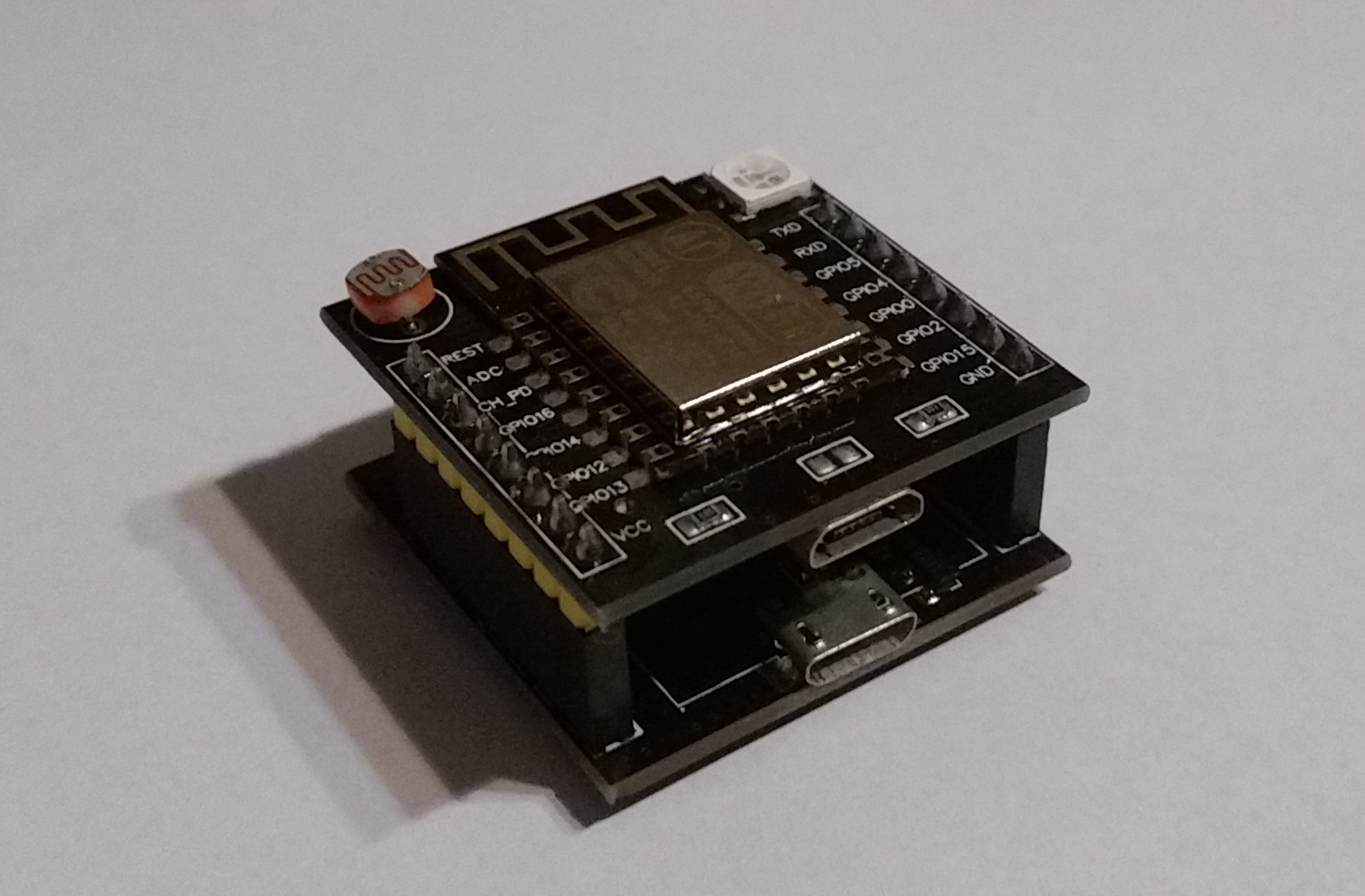
Main Board
In the center you see the heart of this tiny fellow, but it’s accompanied with some useful features too:
- USB port for power supply (only),
- RGB LED diode,
- a photoresistor,
- a simple SPST switch.
But more importantly, it contains convenient 2.54mm headers which allow to plug it into your breadboard.
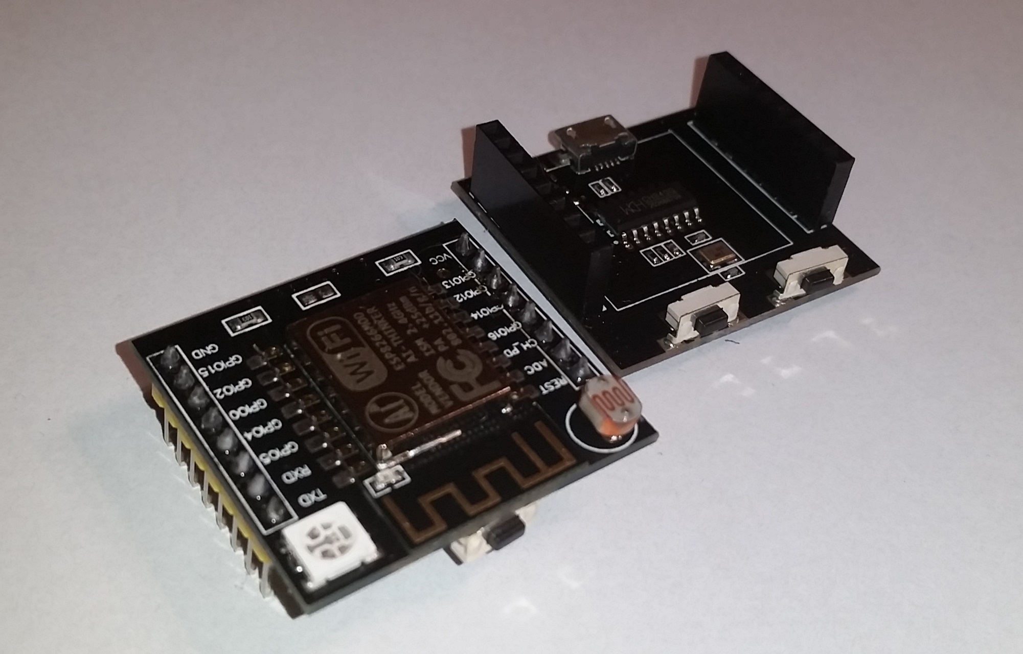
USB Board
It includes (a second!) USB socket, that has to be used for programming the microcontroller. It also has RESET and FLASH buttons. You’ll need to use these buttons during your first program upload.
Software
Now let’s focus on deploying a simple program to the MCU.
Before you go any further, make sure you have Arduino IDE installed.
Setting Up Arduino
Since ESP8266, the main WiFi controller used in this board, is not by default supported by Arduino (why should it? it’s a third party!) we’ll have to take a few extra steps. The good part is that you have to do it only once! 😉
All the instructions are always up to date in the ESP8266 Arduino project, I’ll put them below just for your convenience:
- Open Arduino IDE.
- Go to
File/Preferences(or just press ctrl + ,).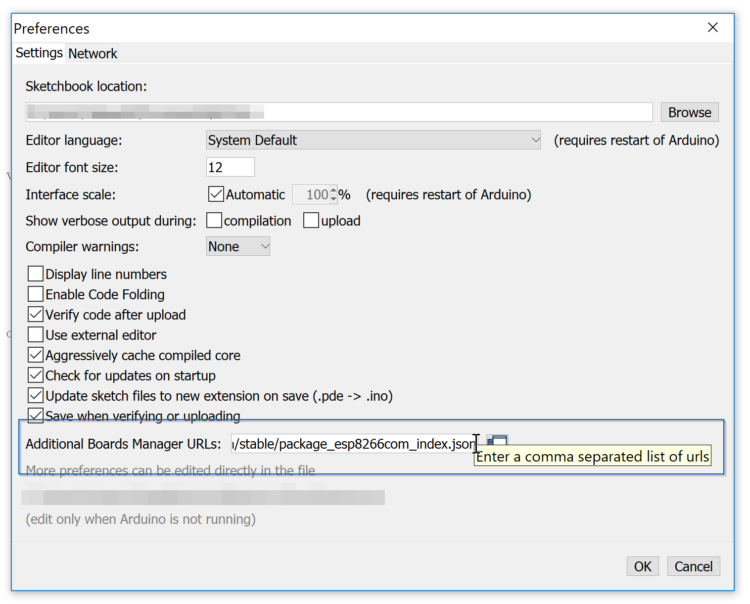
- In “Additional Boards Manager URLs:” field you need to add a link
http://arduino.esp8266.com/stable/package_esp8266com_index.json. In case you have already some value set, you can have multiple values as long as you’ll separate them with commas. - Save.
- Now go to Boards Manager:
Tools/Board: <boardName>/Boards manager…and type in ESP8266, install the matched pacakge.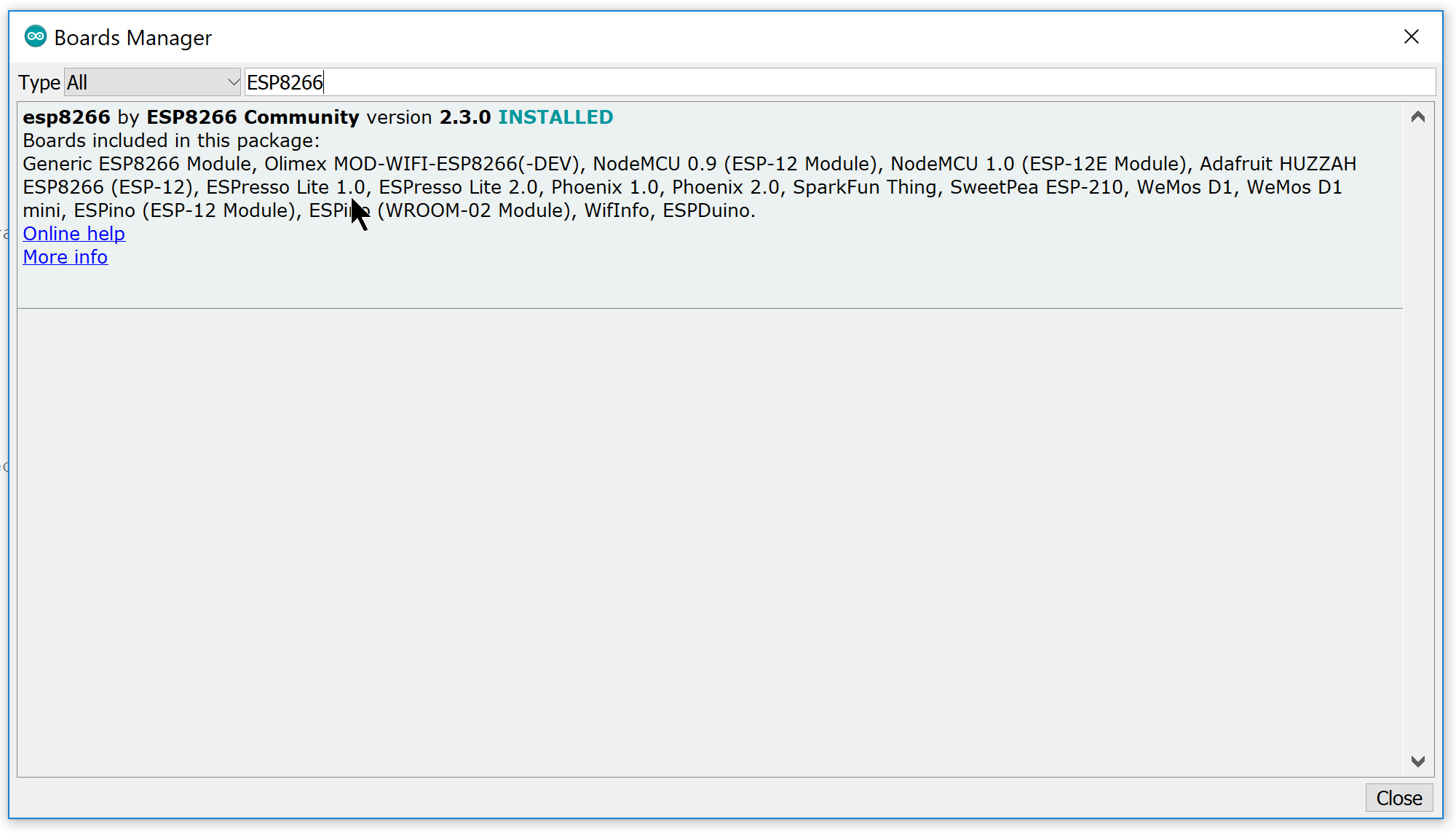
First Sketch
Now we’re ready for coding! First we’ll simply use mighty Blink example to keep things easy.
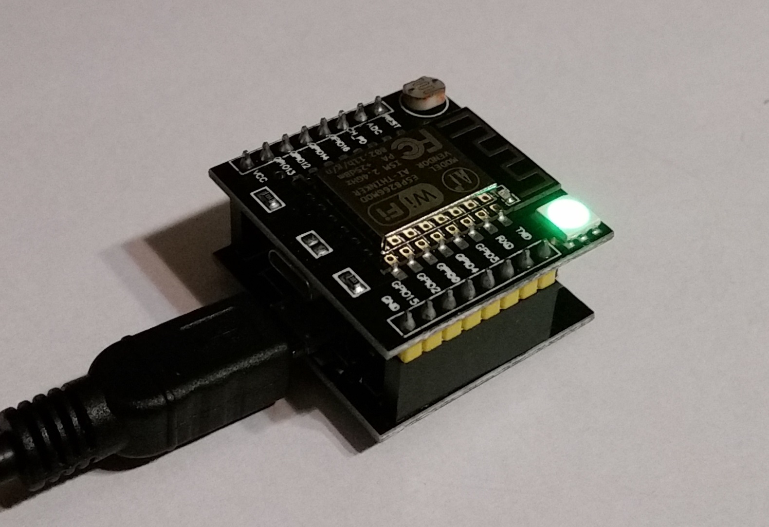
Start by connecting the board to your computer. So slide the top part to the bottom one:
And connect the bottom usb board to your desktop. You’ll see that it will use the default firmware, for me it’s just lighting a green light.
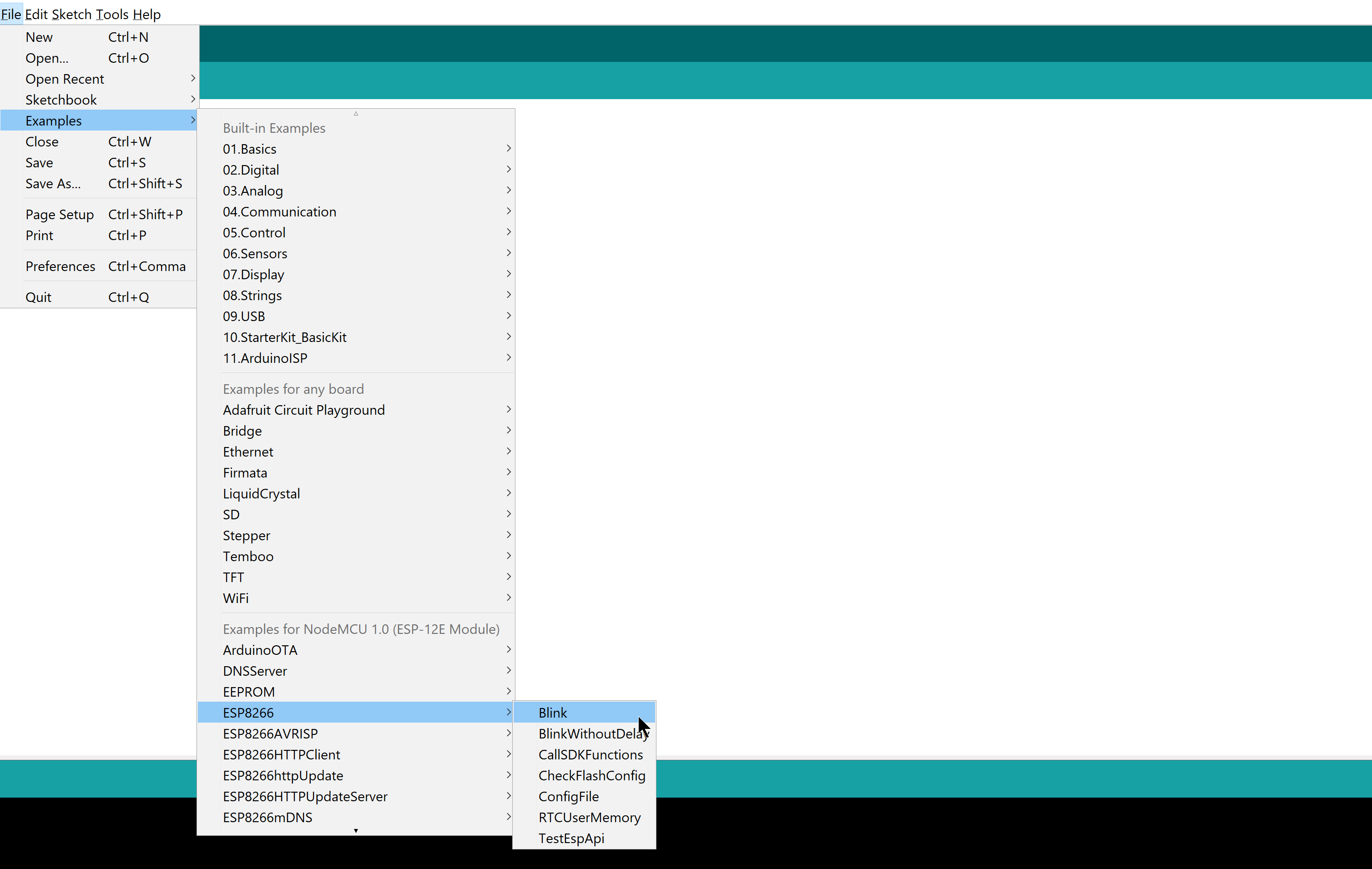
Then open the Blink example provided with ESP8266 Arduino IDE integration:
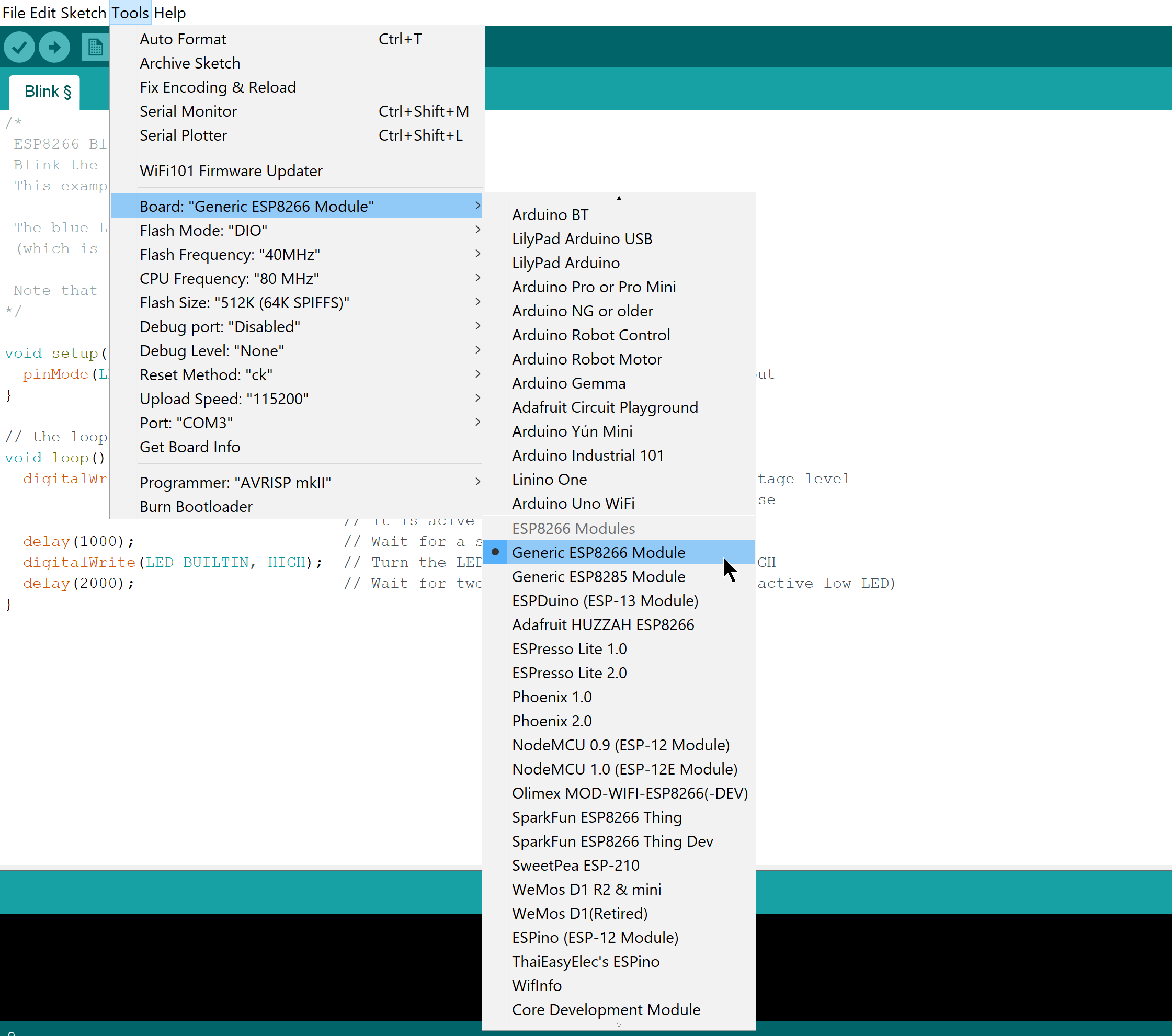
Now it’s important to set the board type. There’s no dedicated type for a “Witty Cloud Development” but “Generic ESP8266 Module” will do. Also you need to chose the correct port, in my case it is COM3.
Now let’s switch LED_BUILTIN to 15 so that it will use a red LED, so you should end up with the code that looks like that:
void setup() {
  pinMode(15, OUTPUT);     // Initialize the 15 pin as an output
}

// the loop function runs over and over again forever
void loop() {
  digitalWrite(15, LOW);   // Turn the LED on (Note that LOW is the voltage level
                           // but actually the LED is on; this is because
                           // it is acive low on the ESP-01)
  delay(1000);             // Wait for a second
  digitalWrite(15, HIGH);  // Turn the LED off by making the voltage HIGH
  delay(2000);             // Wait for two seconds (to demonstrate the active low LED)
}
First Upload
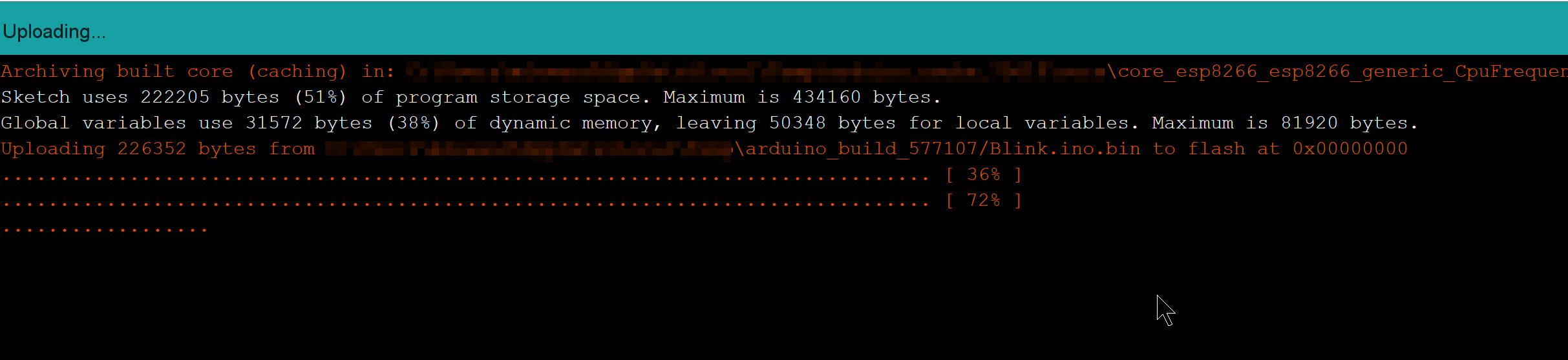
Now the first upload could be a bit tricky. If you attempt to upload straight from here you’ll see an error:
Archiving built core (caching) in: X:\tmp\core_esp8266_esp8266_generic_CpuFrequency_80,FlashFreq_40,FlashMode_dio,UploadSpeed_115200,FlashSize_512K64,ResetMethod_ck,Debug_Disabled,DebugLevel_None_____352fbb4a515bda32a7f9dcf0d11c00ac.a
Sketch uses 222205 bytes (51%) of program storage space. Maximum is 434160 bytes.
Global variables use 31572 bytes (38%) of dynamic memory, leaving 50348 bytes for local variables. Maximum is 81920 bytes.
error: failed reading byte
warning: espcomm_send_command: cant receive slip payload data
error: failed reading byte
(…)
warning: espcomm_send_command: cant receive slip payload data
warning: espcomm_sync failed
error: espcomm_open failed
error: espcomm_upload_mem failed
What you need to do is just to hold FLASH, press and release RESET and release FLASH button.
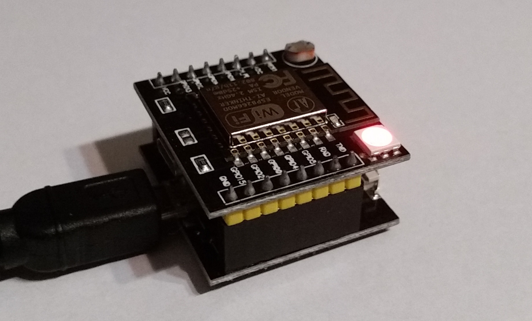
As a result small blue LED will blink for a fraction of a second, and RGB diode will turn green-blue. Now you’re ready to upload your sketch, go on and use Sketch \ Upload option (or if you feel like a keyboard hero just hit ctrl + u 😉).
And take a look at your board now it blinks red, great! Now that you know how to upload your sketches let us utilize the WiFi part!
WiFi Example
I found WiFiScan example to be the simplest one in the package. It essentially lists you nearby networks discovered by the ESP8266 MCU. So, let’s get this thing going!
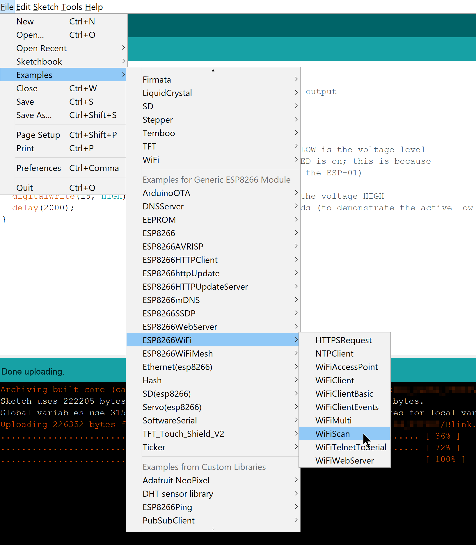
First, go to Examples \ ESP8266WiFi \ WiFiScan:
Make sure your board is connected and that you pressed FLASH, RESET switch sequence just as in the previous example. After that press ctrl + u to compile and upload the sketch.
Once the sketch is uploaded just press ctrl + shift + m to open up a serial port monitor. You’ll see that your ESP8266 is checking for WiFi networks, and send the list through serial port:
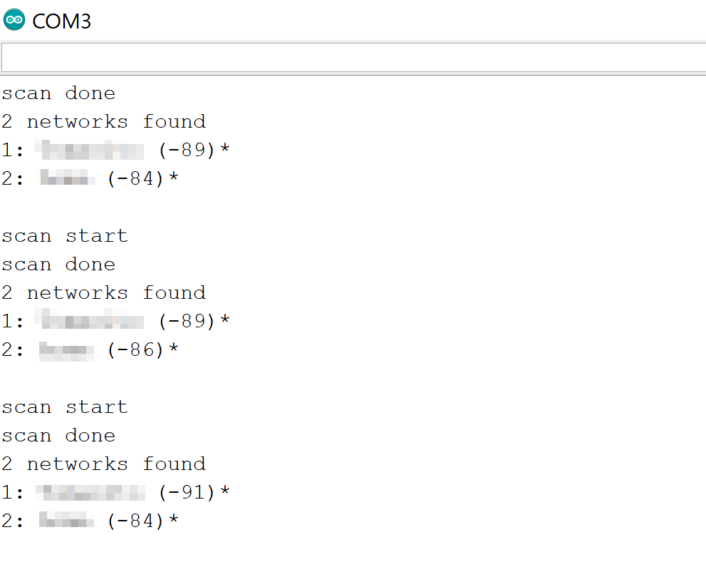
So here you have a simple WiFi example. Of course it did not involve connecting to your network, and actually communicating with other devices. If you wish to try out a more advanced example I’ll cover it in another blog post.
Pinout
I did not receive any datasheet from where I bought the board, so I had to search the pinout around the net. I’ll include it below to save you the trouble:
SPST_SWITCH = 4;
PHOTO_RESISTOR = A0;
GREEN_LED = 12;
BLUE_LED = 13;
RED_LED = 15;
Final Thoughts
I must say that I’m impressed how featureful this board is for it’s cost. You get a very simple, extremely quick to prototype board in just couple of bucks! I bought it for 7$ (just because electronics isn’t too cheap here in Poland), but I can see on eBay it’s around 4$, it’s even cheaper on AliExpress.
It does have some disadvantages though, first of all is that… it’s easy get it started but (with USB board connected) it’s not easy to actually plug it into a breadboard. But… The ability to being able to quickly test something is much more important to me.
I have already had a good time with ESP2866 thanks to this board, and I’ll definitely put some more posts on that in the future.
Written on August 1st , 2017 by Marek Lewandowski